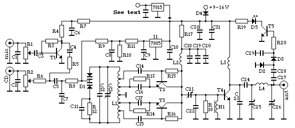
Fig 1: Wiring diagram for the 1W Ve**nica

Fig 1: Wiring diagram for the 1W Ve**nica
The TX has a built-in "mini-mixer" which makes it possible to use it without any external mixing table. This consists of the transistor T1, which amplify the mike signal before it gets combined with the CD (or tape) one. R1 and 2 are adjustable resistors (potentiometers) which is used to set the audio level (see the tuning section).
The components between R8 and C21 is the oscillator, the part which generates the radio signal. The diode D1 is a so-called "varicap", which can be seen as an variable capacitor, controlled by the audio signal. That, C12, 13, and the coil L1 decides the frequency. The oscillator is actually two oscillators, operating in antiphase around 50MHz. When the two signals are combined, they make a 100MHz signal. This setup is generally much more stable than one oscillator operating directly at 100MHz. The signal is then amplified up to 1W in T4.
To the far right is a the tuning aid, which rectifies a part of the output and controls the LED D5. The higher output, the brighter is D5.
|
 Fig
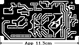
4: PCB layout for the 1W Ve**nica Fig
4: PCB layout for the 1W Ve**nica |
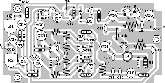
The components should be placed as flat as possible on the board, with short wires. The transmitter should be mounted in a shielded metal enclosure (connected to circuit ground), like these die-cast aluminum "block" enclosures. Use 3mm bolts with 5-10mm spacers, to create a good electrical connection.
The transistor T4 needs a little heatsink to cool it off. This could be made from a 2cm long piece of metal pipe, with slightly smaller diameter than the transistor. Cut a lengthways slot in the pipe, so it can be bent a bit out, and put on. Make some holes in the lid above it, to ensure air circulation. The heatsink is connected directly to the collector of T4, so make sure it doesn't get too close to the lid (app 5mm distance). The mike and CD connections could be done with 3.5mm jack plugs, while the power could be done with a such a plug that's often used with power supplies. For the antenna output I would recommend BNC plugs (like those used with some computer networks). The sockets' ground side should have a good connection to the enclosure, and internal wire should be made as short as possible (especially important with the antenna connection!). It's wise to mount D5 in the lid, so you constantly can see if the transmitter is operating properly.

Fig 5: Component placement
Tuning
In order to make the transmitter operate properly, it needs to be tuned. To
this I'll recommend you to make a so-called dummy-load, which makes it easier to
distinguish the main signal from weaker ones. This is a resistor of 47 or 68
ohms (corresponding to the antenna you intend to use), which is soldered to an
antenna plug. Make sure the resistors can handle the power from the transmitter,
and that they're not wire-wound. Don't ever turn on a transmitter without
antenna or dummy, or else the output stage might blow.
Set all the trimmer capacitors to middle position (the upper plates cover
half the lower ones), connect the dummy to the antenna output and a CD player to
the CD input. When you switch on, the LED should light a bit (if not, try
adjusting C21) and the transmitter operate around 98MHz. Use a small screwdriver
with insulated handle (to not affect the circuit) and tune C21, 25 and 26 for
maximum LED brightness. Then adjust C13 carefully up or down (depends on which
frequency you intend to use) until the LED dims, but not goes completely out.
Then tune the other trimmers until the LED is bright again. Continue this way
until you get the frequency where you want it. Check with a radio to ensure that
you're only transmitting on a single place in the band, if not you might have to
re-tune from the beginning. If you have trouble reaching the ends of the band,
L1 must be changed a bit. Carefully squeeze the turns a bit closer
together to go down in frequency, increase the spacin! ! g to go up.
Now adjust R2 until the CD player sound as loud as the other stations. Be
ware that many stations uses "compression" in order to make the sound
seem louder than it actually is, and if you set it that loud, you might
over-modulate. This might cause noise in neighbor channels, and must be avoided
at all times. Similarly you must be careful not to set the mike (or talk) too
loud, the best is to have an external mixer with some kinda ALC (automatic level
control).
Don't get pissed if it doesn't work at first, transmitters generally requires
a bit of fiddling and patience...