Sonarbugg mottagare
SYSTEM
THEORY
The
transducers are co-resonant near 40 kHz. If the carrier is tuned slightly away
from resonance, frequency modulation of the carrier by audio generates
amplitude modulation at the sending transducer and the receiving transducer.
The pair acts as a slope detector. The receiver recovers audio by rectifying
and lowpass filtering the carrier.
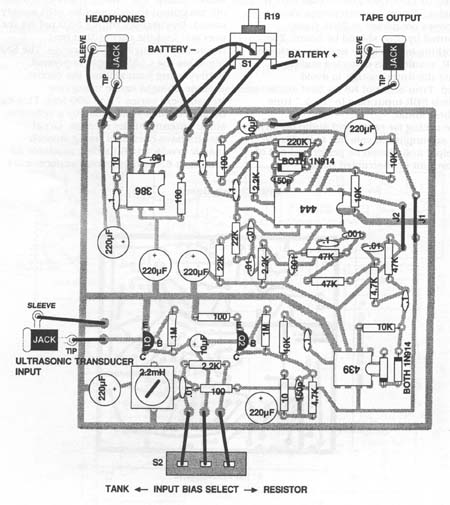
CIRCUIT
FUNCTION
Ultrasonic
transducer couples to the base of Q1, configured as a common-emitter amplifier
by R1. S2 selects collector bias through R2 or tank Li -C2. Ql output couples
through C3 to base of Q2 configured as a common-emitter amp by R4, R5, and R7.
C23 rolls off response above 200 kHz. Q2 output couples through C5 and R8 to
op amp U3, configured as a precision halfwave rectifier by D1, D2, and R9.U3
output (taken at resistor/diode juncture) couples through C6 to U 1-a,
configured as a quasi -18 dB / octave lowpass filter by R10-13 and C7-9.
Cutoff frequency is just above 3 kHz. U1-a output couples to U1-b, configured
as a quasi -18 dB/octave highpass filter by C 10-12 and R14-16. Cutoff is
around 700 Hz.U
1-b output couples through C 18 to U 1-c, configured by R20 and R21 as an
inverting buffer with gain of 40 dB. Cl 9 limits high-frequency response;
diodes D3 and D4 clip the output of the buffer at about 1.2 Vp-p. U1-c output
couples R22 and C20 to tape output jack. U 1-b output also couples through C 13
volume control pot R17, whose wiper couples to the noninverting input of U2.
C14 shunts RF at U2 input. R19 and C17 form the standard snubber. Audio
couples through C16 to headphone output jack.U1-d
is configured as a DC voltage follower whose noninverting input is biased at V+
by divider R23-R24. U1-d output serves as a stable bias reference for U3 and
U1-a/b/c.
C4, C15, C21, C22, R3, R6, and R18 decouple the supply.
PartList
Capacitors
C1,4,15,16,21,22 = 220 uF aluminum electrolytic
C2 = 0.01 uF, 5 percent or better poly
C3,20 = 10 uF aluminum electrolytic
C5,6,13,18 = 0.1 pF coupling
C7,11,12 = 0.01 pF 10 percent or better
C10 0,1uF precent or better
C14 = 0.001 uF ceramic bypass
C17 = 0,1uF ceramic bypass
C19,23 = 150 pF ceramic bypass
Resistors
R1,4 = 1M
R2,14,20 = 2,2K
R3,7,18,22 =100
R5,11= 4,7K
R10,12,13 = 47K
R15,16 = 22 K.
R17 = lOK audio-taper pot
R6,19 = 10
R21= 220K
Semiconductors
D1,2,3,4 = 1N914 or 1N4 14
Q1.2 = 2N3904 NPN
U1 = LF444 quad low-power op amp
U2 = LM386 audio power driver
U3 = MAX439 low power op amp
J1,2 = Jumper
L1 = 2.2 mH variable inductor
S1 = SPST switch (part of R17)
S2 = SPDT switch
Ultrasonic transducer (Panasonic p/n EFR-RUB40K5 or equivalent)
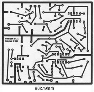
9 V battery. printed circuit board,solder,wire, etc.