Sonarbugg
Strides in RF and IR debugging drove wire specialists to media that escape
detection In standard sweeps.
One such medium is ultrasonic audio.
The sonarbug (SNB) frequency modulates a 40 kHz audio carrier.
CIRCUIT FUNCTION
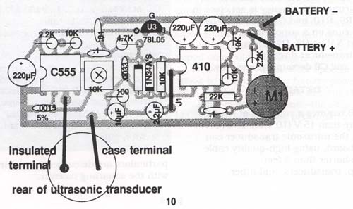
Microphone Ml gets its bias through R1.
M1 output couples through Cl to noninverting input of U 1, biased through
R5 to 1/2 V+ produced by voltage divider R1 -R2.
U1 is configured as a noninverting amp with frequency-dependent gain, set by the
ratio of feedback resistor R6 to the network formed by R4, C4, and C5.
C3 rolls off the response above 4 kHz.
Dl and D2 clip U1 output at about 0.7 Vp-p.
U1 output couples through lowpass network R7-C7 to C8, then to pin 5 of U2, a CMOS 555 timer
configured as an astable multivibrator whose free-running frequency is set close to
40 kHz by R9, R1O, and C10, trimmed by pot R8.
U2 runs on a supply locally regulated at 5 V by U3.
U2 drives the ultrasonic transducer directly.
C1, C2, and C9 decouple the supply.
DETAILS
The SNB requires a supply of at least 6 V but not more than iSV (10 V for a MAX41O).
M1 and the ultrasonic transducer can mount off-board, using high-quality cable preferably shorter than 3
feet.
Tune-up, transducers, and other particulars are discussed in conjunction with the sonarbug receiver.
SNB PARTS LIST
Capacitors
C1,2,9 = 220uF aluminum electrolytic
C3,8 = 0.1uF coupling
C4 = 10uF aluminum electrolytic
C5 = 2,2uF aluminum electrolytic
C6 = 0,0033uF 10% or better
C7 = 0,01uF 10% or better
C10 = 0,0015uF 5% or better
Resistors
R1,2,6,10 = 10K
R3,9 = 2,2K
R4 = 100
R5 = 22K
R7 = 4,7K
R8 = 10K singel-turn
Semiconductors
D1,2 = 1N34A
U1 = MAX410 or TL071
U2 = LMC555 CMOS timer
U3 = LM78L05 5v positive regulator
Miscellaneous
J1 = Jumper
M1 = electret condenser mike
Ultrasonic transducer (Panasonic p/n EFR-TUB40K5 or equivalent)